Incidents
Over the past decades a number of ammonia releases have followed the sudden failure of piping, valves and evaporators in the low-temperature part of refrigeration systems. Careful analysis has shown that many of these failures were caused by condensation-induced hydraulic shock.
The documented cases share a pattern. The failures occur mainly in evaporators and in two-phase suction piping, and mainly when hot-gas defrost begins or ends: at a change in operation, when hot gas arrives quickly at piping that holds liquid. The Mechanism page explains why this combination is dangerous.
Wiencke 2008: spiral freezer at –50 °F
Wiencke (2008) documented in detail the failure of an evaporator coil header in a spiral freezer operating at –50 °F in a frozen-food factory. The accident occurred in June 2007. Within about 20 minutes of the rupture, the ammonia in the room had reached a flammable concentration, and a deflagration followed.
Operating situation: start of hot-gas defrost, after a failure of the liquid-level control.
What happened
The liquid-level controller of the liquid transfer vessel failed, and the vessel was not fitted with a separate mechanical level switch. The vessel filled completely with liquid, and the evaporator coils became nearly full of liquid. The wet return header between the vessel and the coils, on the other hand, was empty.
The defrost sequence relied on a timer. A small “soft” hot-gas valve (½ in.) was meant to build up enough pressure for the main hot-gas valve to be opened safely. The investigation concluded that the soft hot-gas flow had no effect: the pressure did not build up. When the timer then opened the main hot-gas valve (2½ in.), hot gas at a high flow rate reached the liquid in the piping.
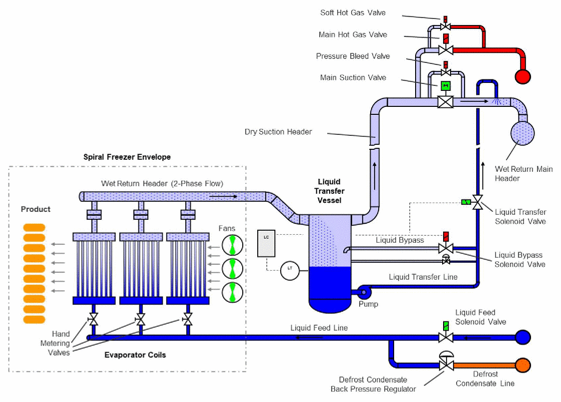
Liquid transfer vessel, control valves and pipework connected to the spiral freezer coils, shown in normal freezing mode. The soft and main hot-gas valves are at the top; the wet return header runs from the vessel to the evaporator coils. Select the image to enlarge it. Source: IIAR 2021 Technical Paper #1, Fig. 2.
The forensic reconstruction
Wiencke’s analysis concluded that liquid resting in a trap above the transfer vessel was driven by the hot gas as a slug along the wet return header. The slug took 0.855 s to reach the end cap of the header. Its impact produced a shock that travelled through the liquid down into the evaporator coil headers, where the fractures occurred. A simplified mathematical model gave a transient pressure of 3,500 to 4,530 psig, with a best estimate of 4,053 psig. The fractures were confirmed by metallurgical and mechanical testing and by finite-element and fracture-mechanics analysis. One coil was not damaged: its vertical header held hot gas, not liquid, at the time of impact.
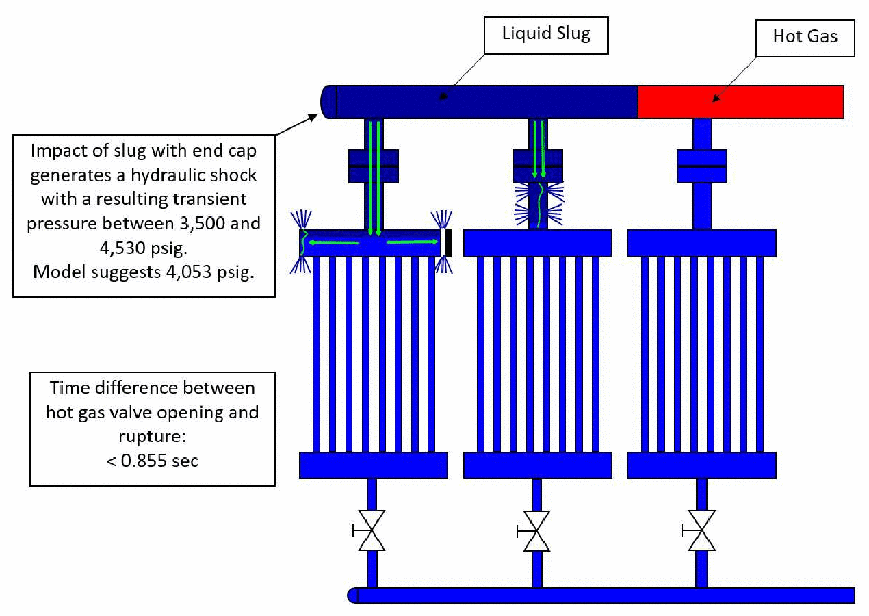
Position of the liquid slug at the time of rupture and the locations of the fractures. The arrows show the path of the shock wave from the end cap of the wet return header into the coil headers. Source: IIAR 2021 Technical Paper #1, Fig. 5, after Wiencke (2008).
Simulation of the accident
The pipework was later simulated with the CFD model developed in ASHRAE RP-1569, using a detailed 3D model of the 10 in. piping with its bends and vertical headers. The base case used the hot-gas flow of the main valve, 5.4 lb/s, with the liquid resting in the trap.
The slug was fully set in motion after about 0.5 s and travelled at about 21 m/s (69 ft/s). A strong shock formed about 0.9 s after the main valve opened, in the vertical header leading down to the coil header where the fractures were found. The peak pressure was about 4,000 psia. The shock found by the simulation lies within the range of the forensic estimate, and its timing agrees with the forensic slug travel time. With only the soft hot-gas flow (0.236 lb/s), no shock formed.
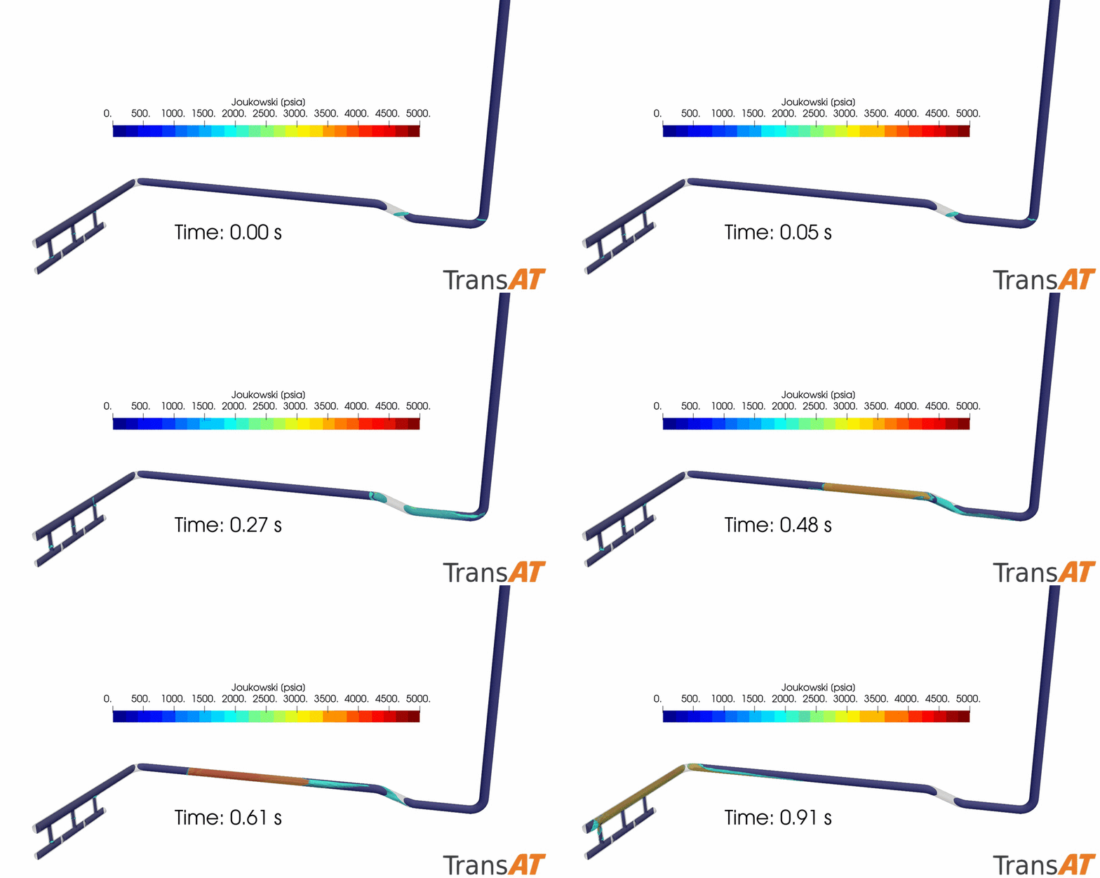
The liquid slug driven by hot gas through the pipework, coloured by the local slug Joukowsky number. The slug leaves the trap on the right, travels along the header and strikes the closed end on the left about 0.9 s after the main hot-gas valve opens.
The last hundredths of a second are shown below in close-up at the closed end of the header. As the slug arrives, the vapour pockets left at the end cap and at the top of the first vertical header shrink and disappear within about 10 milliseconds. Until the last pocket has gone, the pressure in the pipework stays low. Once it has condensed, the liquid strikes the closed end, the pressure there rises suddenly, and the pressure wave travels back along the header and down into the coil headers. This is the sequence described on the Mechanism page, in the real pipework.
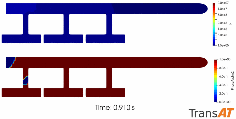
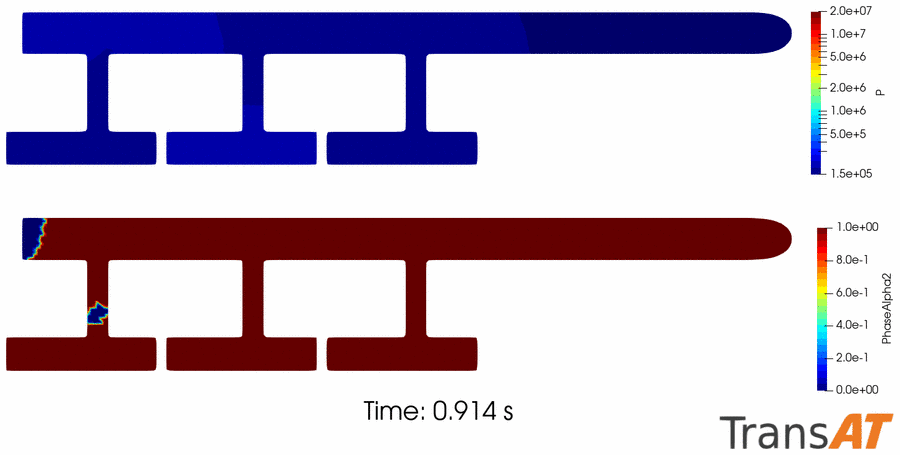
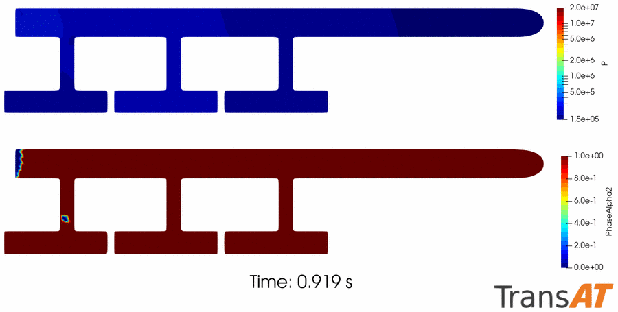
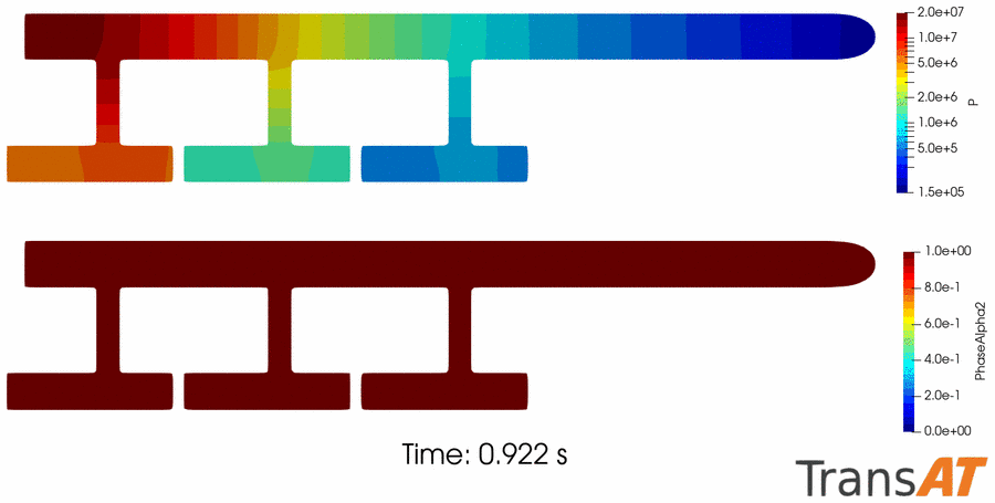
Close-up of the closed end of the header and the coil headers in the last 12 ms before the shock. In each frame, the upper picture shows the pressure (Pa, logarithmic colour scale from 1.5×10⁵ to 2×10⁷ Pa) and the lower picture the liquid fraction (red: liquid, blue: vapour). The vapour pockets at the end cap and in the first vertical header condense (0.910–0.919 s); once they have gone, the pressure at the closed end rises sharply and spreads into the coil headers (0.922 s).
Effect of hot-gas flow and evaporating temperature
The simulation was repeated with lower hot-gas flows and with other evaporating temperatures. The shock grows very steeply with the hot-gas flow: there was no shock up to 2 lb/s, a mild shock at 3 lb/s, and then a rapid rise in shock amplitudes.
| Hot-gas flow (lb/s) | Shock (psia) | Observation |
|---|---|---|
| 0.236 (soft valve, ½ in.) | 0 | No shock; the slug develops a long nose and fills the vertical headers smoothly |
| 1.0 | 0 | No shock in the pipework |
| 2.0 | 0 | No shock; end pipe and headers fill smoothly |
| 3.0 | 450 | Mild shock |
| 4.0 | 2,000 | Strong shock |
| 5.4 (main valve, 2½ in.) | 3,500 | Massive shock |
Shock amplitude against hot-gas flow at an evaporating temperature of –50 °F. Source: IIAR 2021 Technical Paper #1, Table 1.
A lower evaporating temperature makes the shock much stronger. At –10 °F only minor pressure peaks remained; at –60 °F the shock was nearly twice as strong as at –50 °F.
| Evaporating temperature (°F) | Shock (psia) | Observation |
|---|---|---|
| –60 | 6,000 | Massive shock |
| –50 | 3,500 | Massive shock |
| –30 | 850 | Strong shock near the end cap |
| –10 | 380 | Minor pressure peaks |
Shock amplitude against evaporating temperature at a hot-gas flow of 5.4 lb/s. Source: IIAR 2021 Technical Paper #1, Table 2.
Lessons
The analysis supports the recommendations of Wiencke (2008) and of the U.S. Chemical Safety Board (2015):
- Avoid liquid traps. Piping layouts in which liquid can collect and fill the pipe allow a vapour-propelled liquid slug to form. In this accident, without the liquid in the trap there would have been no shock.
- Remove the liquid before admitting hot gas. Evaporator coils should be nearly empty of liquid before hot gas is introduced. This requires a pump-out, push-out or boil-off step in the defrost sequence, with safeguards interlocked with the controls.
- Use pressure feedback, not timers. Before the main hot-gas valve is opened, a pressure transducer or pressure switch should confirm that a safe pressure has been reached. At the end of defrost, the coils should likewise be confirmed depressurised before the main suction valve is opened.
- Size and sequence the hot-gas valves. A small first hot-gas flow does not produce a shock; the hazard comes from opening a large valve without verified pressure build-up. See Guidance for valve sizing.
- Make interrupted sequences fail safe. If a defrost sequence is interrupted, for example by manual intervention or a power outage, the system should return to a safe state.
- Treat low evaporating temperatures as higher risk, and use materials suited to low temperatures and to possible shocks, such as low-temperature carbon steel or stainless steel.
Other documented cases
Loyko (1989, 1992). Reported several failures in the piping of ammonia refrigeration plants: a 1¼ in. end plate blown off a pan-coil header, a 4 in. weld cap blown off a wet suction return line, and a 16 in. end plate blown off a wet suction line. From an analysis of the operating conditions that led to the pressure peaks, Loyko recommended piping designs and operating conditions that make shocks less likely.
Glennon and Cole (1998). Investigated hydraulic shock events in an ammonia refrigeration system that did not lead to failure, with recommendations for piping and operating conditions to reduce the occurrence of shocks.
U.S. Chemical Safety Board (2015): Millard Refrigerated Services, Theodore, Alabama. On 23 August 2010 a hydraulic shock caused the failure of a 12 in. suction pipe on the roof of the facility. About 32,100 lb of anhydrous ammonia were released. One worker on site and 152 workers off site were exposed; 32 were admitted to hospital, four of them to intensive care. The incident had many points in common with the case described by Wiencke (2008). CSB investigation page.
References
- Wiencke B. (2008). A case study of pipework fracture due to hydraulic shock in an ammonia system. IIAR Technical Paper, 30th Annual Meeting, Colorado Springs, CO.
- Narayanan C., Wiencke B., Loyko L. (2021). CFD analysis of pipework fracture due to hydraulic shock in an ammonia refrigeration system. IIAR Technical Paper #1, Natural Refrigeration Online Conference.
- Loyko L.L. (1989). Hydraulic shock in ammonia systems. IIAR 11th Annual Convention, Austin, Texas.
- Loyko L.L. (1992). Condensation induced hydraulic shock. IIAR Technical Paper 165, 14th Annual Convention, Miami, Florida.
- Glennon C., Cole R.C. (1998). Case study of hydraulic shock events in an ammonia refrigeration system. IIAR 20th Annual Convention, Colorado Springs, Colorado.
- U.S. Chemical Safety and Hazard Investigation Board (2015). Millard Refrigerated Services ammonia release. Investigation report.