Mechanism
Condensation-induced water hammer occurs when vapour at high velocity is introduced over or behind liquid lying in a pipe. The vapour drives the liquid as a slug towards a closed end, the vapour trapped ahead of the slug condenses, and nothing is left to slow the slug down before it strikes and causes a pressure surge.
In ammonia refrigeration the same event is usually called condensation-induced hydraulic shock (CIHS). This page describes the sequence of events, the operating situations in which it occurs, and why the resulting shock is so difficult to guard against. The terms used are collected in the glossary at the end of the page.
The sequence of events
Consider a horizontal pipe that is partly filled with liquid and closed at its far end, for example by an end cap or a closed valve. Vapour now enters the pipe at high velocity.
- Waves form. The vapour flowing over the liquid drags on its surface. The surface forms waves, which grow as the vapour flow continues.
- A liquid slug seals the pipe. One of the waves grows until it reaches the top of the pipe. The liquid now fills the whole cross-section and forms a slug, with vapour behind it and a pocket of vapour trapped ahead of it.
- The vapour drives the slug. Further flow of vapour from upstream pushes the slug towards the closed end. The trapped vapour ahead of the slug is compressed. In a pipe filled with a non-condensing gas, this compressed gas would act as a cushion and slow the slug down. Here the trapped vapour condenses instead: onto the oncoming slug, into the liquid mixed with it, and on the pipe walls.
- The slug strikes. With no cushion left, the slug meets no resistance to its motion and collides with the closed end. The trapped vapour collapses, the slug is stopped almost instantly, and the pressure rises sharply: this is the hydraulic shock or the condensation-induced water hammer.
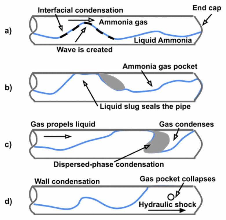
Progression of a condensation-induced shock event: (a) the gas flow raises a wave on the liquid layer, with condensation at the interface; (b) a liquid slug seals the pipe and traps a gas pocket; (c) the gas propels the slug while the trapped gas condenses; (d) the gas pocket collapses at the end cap and a hydraulic shock forms. Source: IIAR 2021 Technical Paper #1, Fig. 1.
Condensation plays two parts in this sequence. When vapour flows into a pipe that is closed at the far end, the vapour already in the pipe has to be compressed. The pressure rises and the vapour slows down. Without condensation, it would slow down too much for a slug to form. Condensation removes vapour and keeps the flow fast enough to raise waves. Once a slug has formed, condensation removes the trapped vapour ahead of it, so that nothing slows the slug before it strikes.
Where it occurs
Three conditions have to come together: liquid lying in a pipe or flowing slowly, vapour arriving quickly over or behind it, and a closed end or obstruction ahead. These conditions arise mainly when the operation of a system changes, rather than in steady running.
- Hot-gas defrost. In ammonia refrigeration, hot gas is sent into the evaporators to melt the frost. The hot gas enters piping and coils that may still hold liquid. Slugs formed in the two-phase suction lines can run into sections of piping that are closed and have no exit. Reviews of failures in ammonia plants find that they occur mainly in evaporators and two-phase suction piping, and mainly during hot-gas defrost.
- Rapid pressurisation of two-phase systems. Opening a valve that connects a source of high-pressure vapour to a line holding liquid, for example a fast-acting hot-gas valve that opens fully at once, or steam admitted to a line with standing condensate.
- Operational transients. Start-up and shut-down, restart after an interrupted sequence or a power loss, and valve sequences that rely on timers instead of a measured pressure.
- Depressurising liquid lines: flashing and recondensation. In a liquor blow, hot liquor is discharged from a pulp digester through a blow line into a blow tank at lower pressure. Where the pressure drops locally, for instance at a sharp T-junction, the liquid flashes (boils) to vapour. Further along the line, as the liquid head builds up, the pressure recovers and the vapour recondenses. A condensation front then travels back against the flow onto the junction and produces a condensation hydraulic shock, with large thrust forces on the junction.
Similar conditions occur in steam and power plants, in process plants and in CO₂ sequestration, wherever a liquid and its own vapour share a pipe and the operation changes quickly. The usual causes in steam systems are listed on the Guidance page.
In CO₂ injection wells, liquid and vapour CO₂ can be present in the well at the same time, and the collapse of vapour is checked as a possible source of pressure surges. Laboratory tests in a 3.7 m vertical test section found surges of about 3 bar with pure CO₂, against about 20 bar with water. The surge is weaker in CO₂ because its vapour condenses more slowly, its liquid is less dense and more compressible, and the temperature difference between vapour and liquid is much smaller (Coutinho and Hadjicharalambous, 2024).
Three ways a slug reaches a closed end
The research behind this site distinguishes three routes to a shock. They differ in how the moving liquid is formed, and therefore in how much vapour flow is needed to start them.
- A slug formed from a liquid layer. Hot gas flows over liquid lying along a horizontal pipe, and waves grow into a slug as described above. This needs a gas velocity above a critical value (next section). This is the route studied in the experiments of ASHRAE research project RP-970 and in the CFD simulations of RP-1569.
- A pre-formed slug pushed out of a liquid trap. Liquid collects at a low point of the piping, a liquid trap, where it already fills the pipe. When hot gas arrives, it pushes this plug of liquid out as a slug. No waves have to form, so a much smaller gas flow is enough to set the slug moving. This was the route in the Wiencke accident.
- Flash and recondense. No vapour is injected. Vapour forms by flashing where the pressure drops in a liquid line and later recondenses, as in the liquor blow described above. In a blow-line study, filling the line with liquid before the blow removed the vapour source and the shock; re-routing the pipe alone did not.
How a slug forms
Gas flowing over a liquid layer raises waves on it. At low gas velocity the waves stay small. Above a critical velocity they grow until one of them fills the pipe. For gas flowing through an open horizontal pipe, this critical velocity is given by the criterion of Taitel and Dukler (1976).
In the ASHRAE RP-970 experiments, hot ammonia gas was blown into a 20 ft long, 6 in. pipe that was partly filled with liquid and closed by an end cap. Slugs formed only at higher inlet velocities than the Taitel–Dukler criterion predicts. Martin et al. (2007) therefore proposed a modified criterion:
where is the gas velocity based on the full pipe cross-section, the fraction of the cross-section filled with gas, and the gas and liquid densities, the pipe diameter and the acceleration due to gravity. Written as a mass flow of hot gas, with the pipe cross-section,
For ammonia this gives about 0.1 lb/s for a 4 in. pipe and about 1.0 lb/s for a 10 in. pipe. The Guidance page explains how this critical flow is used.
Why a closed pipe needs a higher flow. In a pipe closed at the far end, the vapour already in the pipe has to be compressed to make room, so the vapour slows down along the pipe and with time. Over most of the liquid surface it therefore moves more slowly than at the inlet, and a higher inlet flow is needed to form a slug.
Effect of an elbow upstream. An elbow upstream of the horizontal pipe disturbs the flow and helps waves to start. In the simulations it lowered the critical velocity by about a quarter.
Why relief valves cannot respond
The shock is short and local. In one of the RP-970 tests simulated in ASHRAE RP-1569, the pressure at the end cap rose to over 700 psi and fell back within about 6–7 milliseconds. Sensors further from the end cap saw a smaller peak. The three-dimensional, unsteady, compressible two-phase flow simulation reproduces both the height and the duration of the pulse, and the decrease away from the end cap.
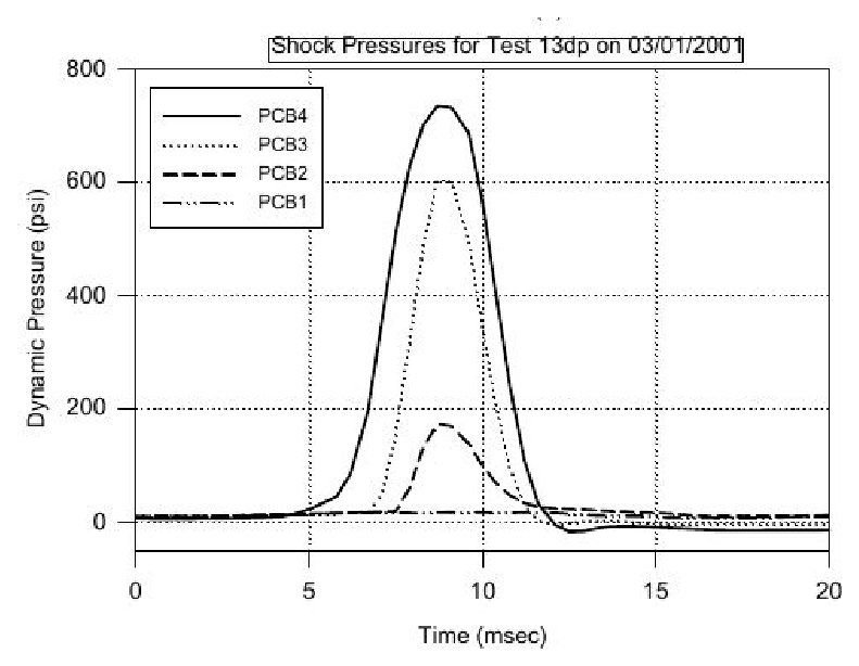
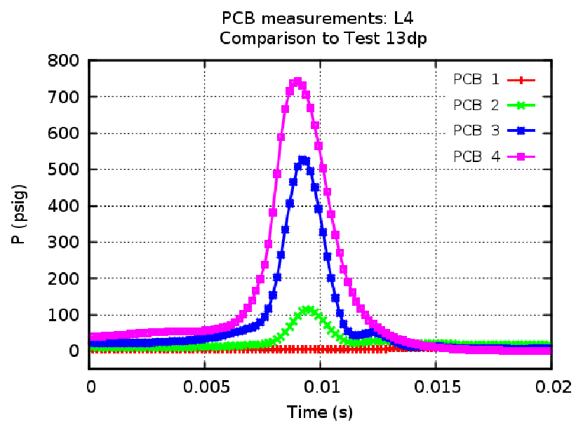
Pressure at four sensors near the end cap during the shock: measurement (left) and simulation (right). The pressure rises and falls within about 6–7 ms, and the peak decreases with distance from the end cap. Source: Narayanan, Thomas and Lakehal (2020), ASHRAE Transactions, Fig. 11.
The shock pressures can be higher than the maximum allowable working pressure of the low-pressure side of a refrigeration system and higher than the setting of its relief valves. A relief valve, however, needs far longer than a few milliseconds to open. Even a relief valve installed close to the location of the shock would not respond in time. Protection therefore has to come from preventing the slug, or from keeping its velocity low, not from relieving the pressure.
The slug Joukowsky number
When a column of liquid moving at velocity is stopped suddenly, the pressure rises by
where is the liquid density and the speed of sound in the liquid. This is the Joukowsky equation of classical water hammer.
For condensation-induced water hammer, the research behind this site uses the slug Joukowsky number
with the slug velocity averaged over its travel along the pipe. Ju measures the shock potential of the moving slug. It is used instead of the peak pressure because the peak pressure is erratic: it depends on the details of the final collapse of the vapour pocket, and repeated RP-970 tests differed by 15–20%. The slug velocity is much more reproducible. Compared with the twelve RP-970 tests, Ju from the simulations agreed with the measured shock to within 18–33% on average, against 43–61% for the simulated peak pressure. The Research page gives the details.
As an example, liquid ammonia at –50 °F has a density of about 696 kg/m³ and a speed of sound of about 1,810 m/s. A slug travelling at 21 m/s (69 ft/s), as in the simulation of the Wiencke accident, gives Ju ≈ 26.5 MPa, or about 3,800 psi. The peak pressure found in that simulation was about 4,000 psia.
Why a one-dimensional surge analysis misses it
Standard water-hammer (surge) analysis treats a pipe as full of a single liquid and follows pressure waves along it. It is the right tool for a valve closure or a pump trip in a liquid-full line; see waterhammer.com for that case. Condensation-induced water hammer is different. The event begins with liquid and vapour side by side, a slug has to form and move, and its speed depends on how fast the vapour ahead of it condenses. None of this is represented in a one-dimensional, single-phase model. Such a model cannot say whether a slug forms, or how fast it will travel.
Glossary
- Condensation-induced water hammer (CIWH)
- A pressure shock caused when vapour drives liquid into a closed end and the vapour ahead of the liquid condenses. The main term on this site.
- Condensation-induced hydraulic shock (CIHS)
- The same event, under the name used in ammonia refrigeration.
- Condensation hydraulic shock
- The term used for the flash-and-recondense case in liquid lines, such as a pulp-digester blow line.
- Hot-gas defrost shock
- Condensation-induced hydraulic shock during hot-gas defrost of an evaporator.
- Steam hammer
- Condensation-induced water hammer in steam systems. The term is also used loosely for any water hammer in steam piping.
- Two-phase water hammer
- Water hammer in a pipe that holds both liquid and vapour (or gas). Condensation-induced water hammer is one form of it.
- Vapour-propelled liquid slug (VPLS)
- A slug of liquid driven along a pipe by the pressure of the vapour behind it.
- Liquid slug
- A body of liquid that fills the whole cross-section of the pipe.
- Stratified flow
- Liquid flowing along the bottom of a pipe with vapour above it, separated by a clear surface.
- Liquid trap
- A low point in the piping where liquid collects and fills the pipe.
- Flashing
- Sudden boiling of a liquid when its pressure falls below the saturation pressure.
- Slug Joukowsky number (Ju)
- The product of liquid density, speed of sound in the liquid and average slug velocity; a measure of the shock potential of a moving slug.
References
- Martin C.S., Brown R., Brown J. (2007). Condensation-induced hydraulic shock laboratory study. Final report, ASHRAE 970-RP.
- Narayanan C. (2018). CFD study of hydraulic shock in two-phase anhydrous ammonia. Technical report, ASHRAE RP-1569, submitted to TC 10.3. ASCOMP USA Inc.
- Narayanan C., Thomas S., Lakehal D. (2020). CFD study of hydraulic shock in two-phase anhydrous ammonia. ASHRAE Transactions 126(2).
- Narayanan C., Wiencke B., Loyko L. (2021). CFD analysis of pipework fracture due to hydraulic shock in an ammonia refrigeration system. IIAR Technical Paper #1, Natural Refrigeration Online Conference.
- Carlson A., Narayanan C., Lakehal D. (2023). Simulation of liquor blow, thrust force, and risk of condensation hydraulic shock in a pulp-digester piping system. ASME J. Pressure Vessel Technology 145, 041401. doi:10.1115/1.4062335
- Coutinho R.P., Hadjicharalambous M. (2024). Demystifying vapor collapse in CO₂ injection wells. 17th International Conference on Greenhouse Gas Control Technologies (GHGT-17), Calgary. SSRN 5010518
- Taitel Y., Dukler A.E. (1976). A model for predicting flow regime transitions in horizontal and near horizontal gas–liquid flow. AIChE Journal 22, 47–55.